Flexible Channel Emulation Workflows on USRPs with MATLAB® and Simulink®
Authors: Nadia Shivarova, MathWorks Wireless Application Engineer and Neil MacEwen, MathWorks Wireless Testbench™ Development
This application note describes a MATLAB® and Simulink® model-based design workflow for developing, deploying, and validating wireless signal processing functions on the FPGA of NI USRP radios using Wireless Testbench™. The note uses SISO terrestrial channel emulation as a representative example. In this workflow, MATLAB is used for scenario definition, waveform and test vector generation, reference modeling, device control, and result analysis, while Simulink is used to architect an HDL-compatible implementation for deployment to the radio FPGA and iterate over fixed-point data conversion. The example demonstrates how a channel emulation design can move from a behavioral model to hardware validation while remaining extensible to broader use cases, such as MIMO, NTN, AI training data generation, and low-PHY exploration in O-RAN systems.
Contents
- Introduction
- Channel Emulation on NI USRP Radios
- Workflow Summary
- Channel Emulator HDL IP
- Validation
- Additional Use Cases
- SISO to MIMO Channel
- NTN Research
- AI Training Data
- O-RAN Research
- OAI Testbeds
- Conclusion
- Appendix
- Tool Requirements
- Appendix
Introduction
Wireless research validation often requires more than simulation and more control than purely over-the-air (OTA) testing can provide. Teams want to define representative wireless scenarios, implement real-time signal processing on hardware, and validate the results against software references without rebuilding the workflow at each step.
This is the role of Wireless Testbench deployment workflow for NI USRP radios. MATLAB remains the environment for scenario creation, standard-compliant waveform generation, reference behavior modeling, control, and analysis. Simulink provides the environment for an HDL-compatible implementation from which synthesizable HDL can be autogenerated. NI USRP radios provide an excellent software-defined radio (SDR) platform where FPGA processing and RF capability are already integrated. Together, these pieces support a approach to hardware prototyping and validation that is practical and repeatable for wireless algorithm research and development. This established methodology has been successfully demonstrated for much larger and more complex designs, such as NR 5G SIB1 receivers.
Channel emulation is valuable when wireless designs need realistic but repeatable test conditions. Receiver behavior, synchronization performance, beamforming decisions, link adaptation, and waveform robustness all depend on delay, multipath fading, and UE mobility. OTA testing remains important, but it is harder to control and repeat under identical conditions.
Deploying a channel emulator IP on an NI USRP provides a practical hardware-in-the-loop (HIL) solution for the prototype and validation of wireless systems. The radio combines FPGA processing and RF capability in one platform, and the channel processing function can run in the live signal path while still being reconfigured from MATLAB. This allows teams to move beyond offline analysis and evaluate behavior on real hardware under controlled conditions.
Although the current example is based on a terrestrial, multipath, ray tracing scenario, the same general workflow is extensible. It can be adapted to additional channel paths, MIMO, NTN configurations, and controlled training dataset generation for AI workflows. See the Additional Use Cases section for more information.
Channel Emulation on NI USRP Radios
The channel emulation example can be found in the Wireless Testbench documentation. Figure 1 below demonstrates a simplified MBD workflow for design and validation to demonstrate four main capabilities.
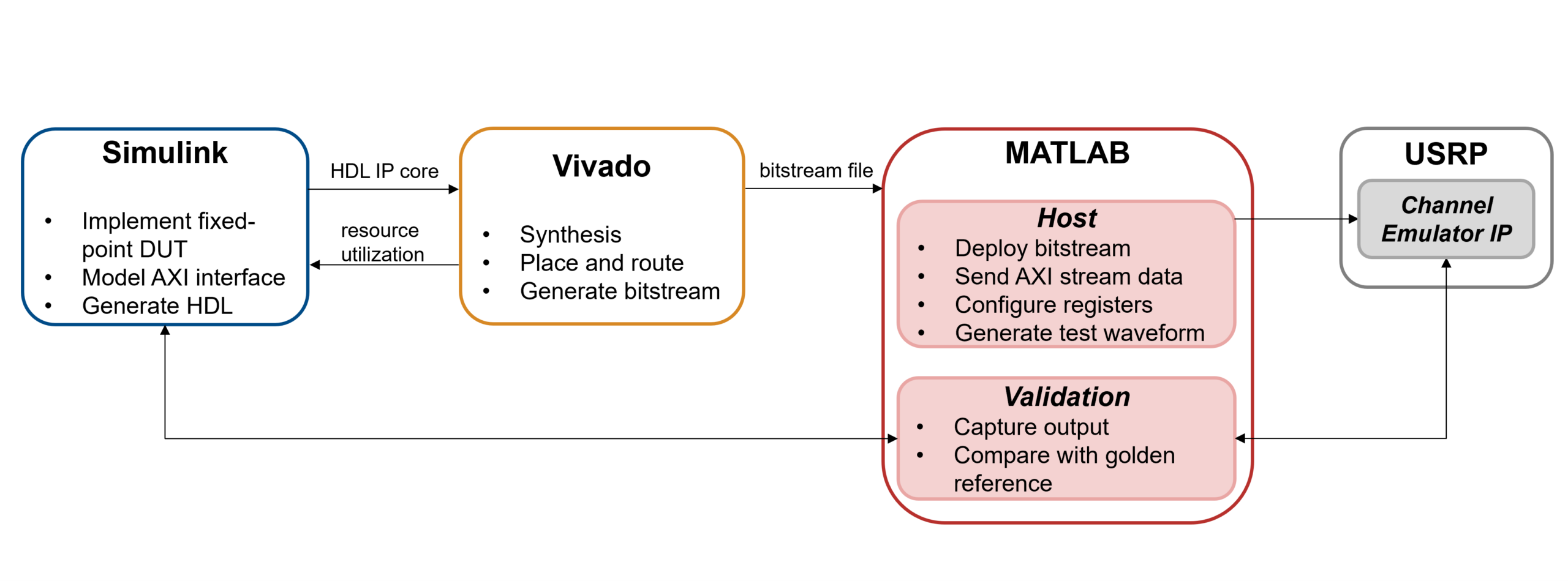 Figure 1: MBD workflow
- A MATLAB test bench that generates required path delays and gains based on a terrestrial ray tracing scenario.
- A fixed-point, HDL-compatible Simulink implementation of a multipath channel emulator device-under-test (DUT) implementing integer and fractional delays.
- Deployment of the design to a supported NI USRP FPGA using the Wireless Testbench deployment workflow.
- A host MATLAB I/Q streaming configuration and validation of the deployed design against a software golden reference.
Workflow Summary
At a high level, the Wireless Testbench deployment flow can be summarized in five stages shown in Figure 2.
 Figure 2: Wireless Testbench USRP deployment workflow
- Set up the environment, toolchain, and saved radio configuration.
- Model the wireless algorithm in MATLAB and then Simulink. Convert from floating to fixed-point data types. Validate functional behavior and AXI interfaces.
- Configure the design for the USRP target and map AXI interfaces.
- Generate the HDL IP re, wrap as an RFNoC block, and integrate the design externally. Obtain the bitstream file.
- Generate and use the MATLAB host interface script to program the device, connect to, and control the deployed design for final HIL validation.
This workflow is supported interactively via the Simulink toolstrip. Or, for CI/CD pipeline automations, there is a MATLAB API, as shown in Figure 3.
 Figure 3: Simulink HDL Code toolstrip
This note does not restate the full deployment procedure. Instead, it uses the channel emulation example to show why this flow is valuable and what it enables in practice.
Channel Emulator HDL IP
The channel emulation example is a concrete instance of the workflow described above. A high level diagram of the operation on the USRP is shown in Figure 4.
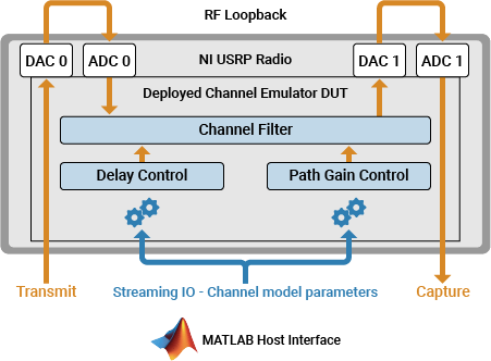 Figure 4: Deployed channel emulator DUT
A MATLAB terrestrial ray tracing scenario, as shown in Figure 5, is used to extract channel parameters, including path delays and gains using comm.RayTracingChannel. The method used is shooting and bouncing rays (SBR) with a map and building information from an Open-Street Map (OSM) file. Building materials, antenna beamforming configurations, and reflections and diffractions can be modelled. MATLAB also provides the software golden reference through comm.ChannelFilter, so the intended behavior of the HDL channel is known before hardware deployment to catch issues early and save validation time. For this scenario, the model is configured for 11 channel paths via MATLAB variables.
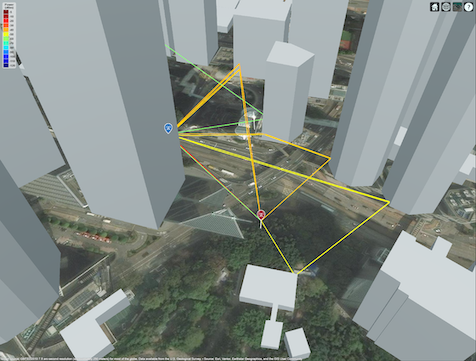 Figure 5: Terrestrial ray tracing scenario
The Simulink model shown in Figure 6 maps that behavior into an HDL-compatible, fixed-point arithmetic DUT implementation of a channel filter with AXI4 Stream interfaces and registers. The design uses highly optimized blocks for HDL code generation, such as reprogrammable discrete FIR filters, complex multiplications, and counters to implement streaming logic, per-path delay handling, complex gain application, and path combination. This makes the model suitable for FPGA targeting while preserving a clear connection to the original channel concept.
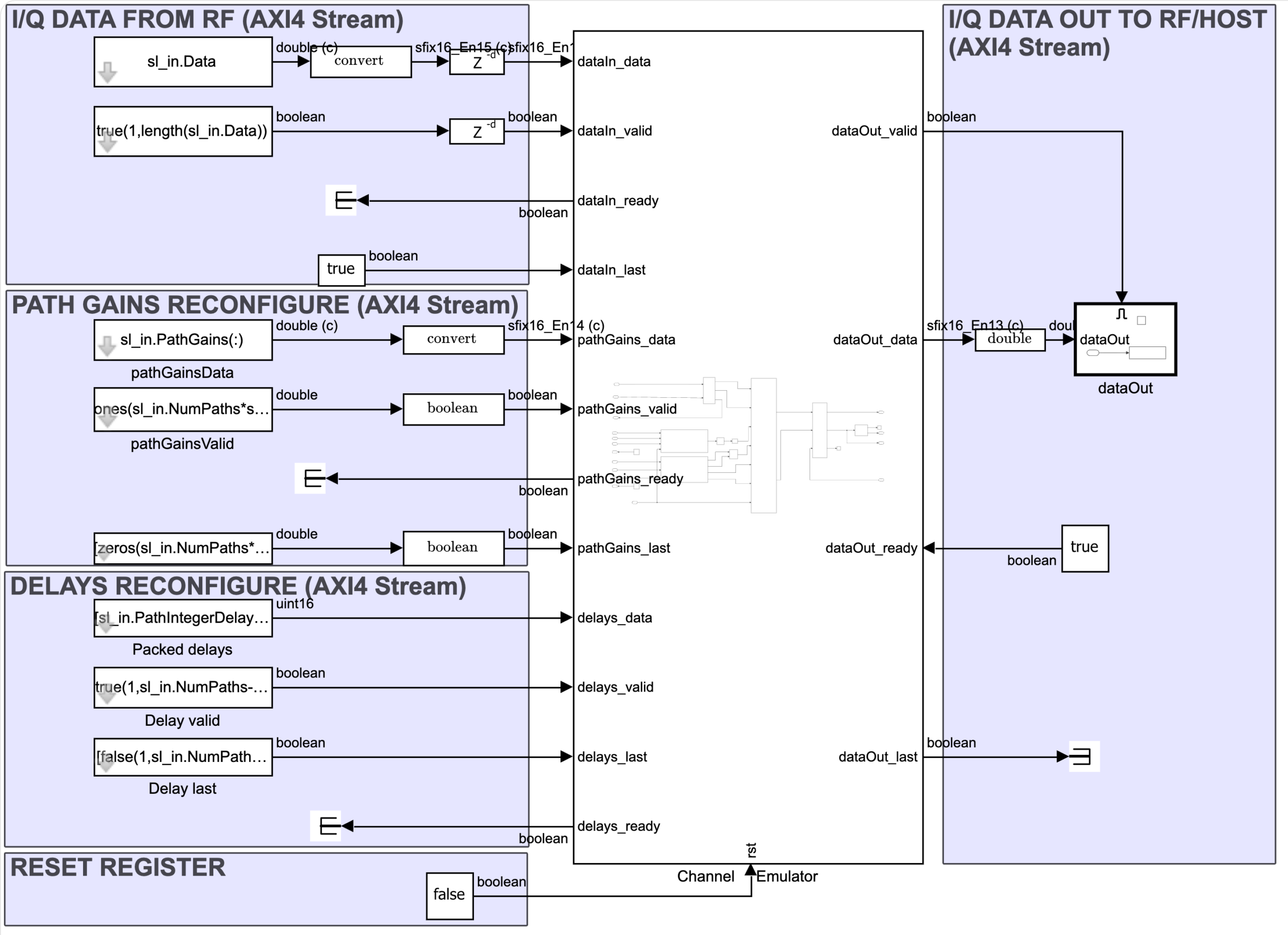 Figure 6: Channel emulator IP implementation model
The next step is to choose the USRP device to target, including FPGA rate and required streaming interfaces. This is shown in Figure 7.
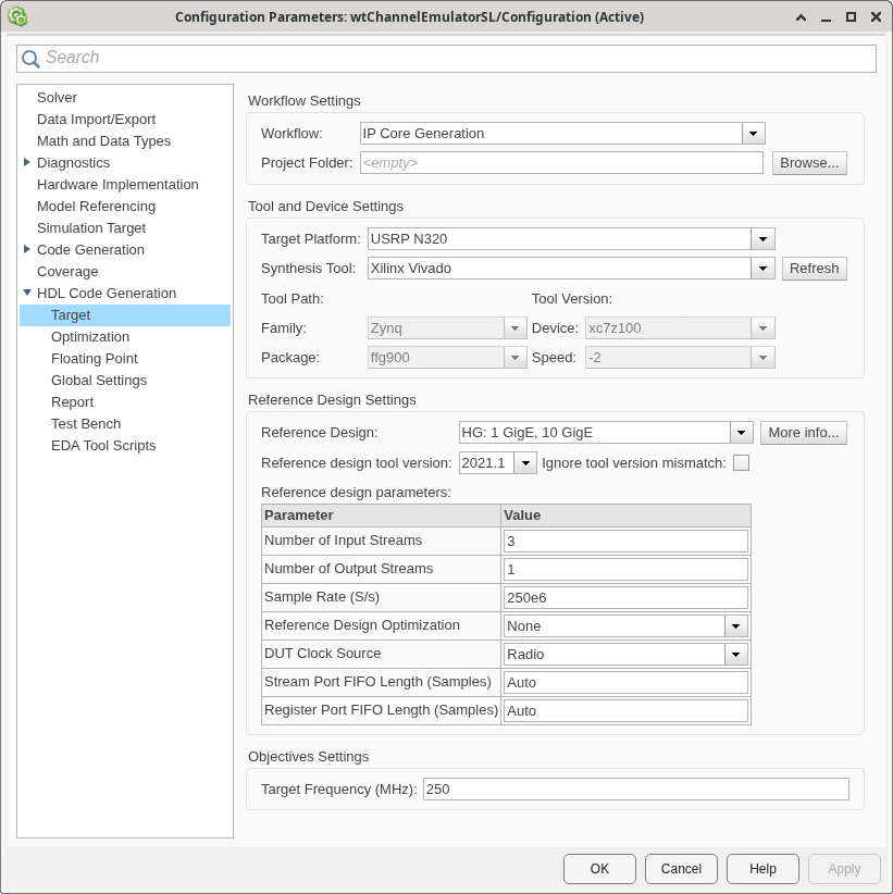 Figure 7: Radio and DUT configuration parameters
Then, select the interfaces described at the DUT boundaries to map to actual radio interfaces as they were labeled in the model. For example, map DUT data inputs to the radio frontend and DUT outputs back to the MATLAB host for validation.
The automated deployment flow generates a device-agnostic HDL IP core, which is then wrapped as an RFNoC block. Vivado is launched in a shell to integrate the design and generate the bitstream file and additional auxiliary files. Host MATLAB artifacts can also be autogenerated and are pre-populated with required functions to deploy the design to the FPGA, stream data in and out, or update registers.
Validation
Validation is an important part of this example, and it is one of the strongest arguments for using this workflow.
Once the fixed-point model is built, it is important to compare the output against the floating-point MATLAB reference. This helps determine if the fixed-point data types are appropriate for precision, range and scaling. Figure 8 shows a simple comparison of the outputs where the max error seen is within an acceptable tolerance of 1e-4.
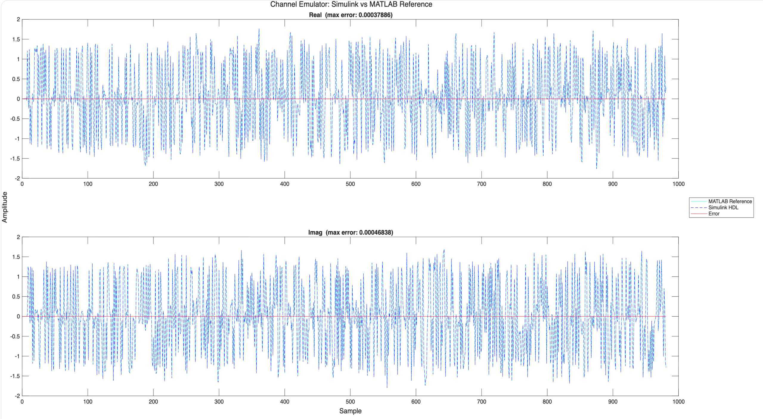 Figure 8: Validating quantization error between floating- and fixed-point models
The next stage is to iterate over the speed and area requirements on the FPGA. This iterative process requires making tradeoffs between pipeline latency, impacting speed, and resource sharing, impacting area. HDL Coder™ can help automate such optimizations. For more information, consult the relevant documentation. The entire RFNoC design was synthesized for 200 MHz. Table 1 shows representative resource utilization only for the channel emulator HDL IP.
| USRP Target | LUTs (%) | FFs (%) | BRAM (%) | DSP (%) |
| X310 | 5579 (2.19) | 16363 (3.22) | 51 (3.21) | 364 (23.64) |
| X410 | 5661 (1.33) | 16856 (1.98) | 38 (1.78) | 364 (8.52) |
Table 1 Resource utilization for channel emulator IP
To enable scaling up to MIMO, this model allows DSP resource sharing to be set via a MATLAB variable. This would significantly reduce DSP resources at the expense of latency as the number of input and output channels grow and consume more resources.
Once the channel emulator IP is running on the radio, MATLAB can be used to stimulate the design by pushing data from the radio frontend to the DUT or sending an AXI4 stream of complex I/Q data directly from MATLAB via Ethernet. Code snippets of functions to set up the radio and perform the validation are given below:
% Setup radio and download bitstream
device = usrp(radio);
programFPGA(device, ...
         "build_N320_HG/build-N320_HG/n3xx.bit", ...
         "build_N320_HG/build/usrp_n320_fpga_HG.dts");
describeFPGA(device, "wtChannelEmulatorSL_wthandoffinfo.mat");
...

% Select physical antenna ports on device
device.TransmitAntennas = "RF0:TX/RX";
device.CaptureAntennas = "RF0:RX2";
...

% Initialize FPGA and send data using AXI4 stream
dut = fpga(device);
writePort(dut, "pathGains_data", sl_in.PathGains(:,1));
writePort(dut, "delays_data", delays);
...

% Set up test vector
txData = int16(impulse * 2^15);
captureLen = impulseLen * 5;

...
% Transmit continuously test vector into FPGA
transmit(device, txData, "continuous");
device(captureLen);
% Capture data back to host from output of FPGA for validation
[dataOut, numSamps] = capture(device, captureLen);
In the same manner, MATLAB can capture data at the output of the DUT for validation. In the current example, this includes checking impulse-response behavior against the golden reference and examining the frequency-selective behavior emulated by the channel based on the original ray tracing scenario, as shown in Figure 8.
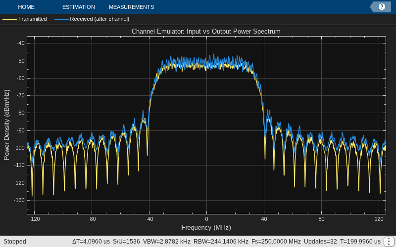 Figure 8: Spectrum analyzer visualization of I/Q data
This closes the loop between model and hardware. The same environment that defined the channel also evaluates whether the deployed implementation behaves as expected.
Additional Use Cases
Although the current example is focused on a terrestrial multipath scenario, the workflow is relevant to several broader use cases.
SISO to MIMO Channel
The methodology is not limited to SISO. As the number of antennas and links grow, the design becomes more demanding in terms of interfaces, memory, and FPGA resources, but the same MBD and deployment workflow applies. Simulink’s ability to handle data vectors creates a natural extension to a MIMO channel emulator. That makes the example a useful stepping stone toward MIMO and beamforming studies. For further up-scaling and synchronizing time and phase across multiple USRPs using the OctoClock, see Connect and Synchronize Multiple NI USRP Radios example.
NTN Research
The workflow is also extensible toward non-terrestrial network (NTN) scenarios. In these cases, Satellite Communications Toolbox can help derive orbit scenario parameters, such as doppler and latency. 5G Toolbox™ nrTDLChannel or nrCDLChannel 3GPP NTN profiles can configure the path gains and delays. For more information on NTN channel modeling, see Model NR NTN Channel.
AI Training Data
Channel emulation can also support AI and machine learning workflows. A controllable deployed setup can be used to generate labelled training and validation data under repeatable wireless conditions. By sweeping channel parameters deliberately, teams can create datasets with clearer provenance and more systematic scenario coverage than uncontrolled OTA capture alone. Explore the Capture and Label NR and LTE Signals for AI Training example to see how USRPs can be leveraged for this purpose.
O-RAN Research
Deploying processing to the USRP FPGA can help isolate low-PHY behavior from higher-layer or software-based processing. That makes the workflow relevant to O-RAN-style split experimentation, where lower-layer timing behavior may need to be studied independently of the rest of the stack. For more information, explore HDL OFDM Transmitter and Introduction to Custom OFDM on NI USRP Radio examples.
OAI Testbeds
The same channel emulation concept can fit into broader SDR and open testbed environments. In OpenAirInterface-style systems and related research setups, a controlled channel stage can complement higher-layer experimentation by adding repeatable wireless behavior to the overall platform.
Conclusion
This application note uses channel emulation to illustrate a broader MATLAB and Simulink Wireless Testbench workflow for NI USRP radios. The value of the workflow is not only that it can produce a flexible, working FPGA deployment, but also that it preserves continuity from scenario definition to deployed validation.
MATLAB supports the front end of the process through modeling, test vector waveforms, and golden references. Simulink provides the environment to design and test the HDL-compatible model. Deployment using Wireless Testbench in MATLAB provides the bridge to USRP hardware, host control and analysis layer for HIL validation.
Channel emulation is a strong example because it demonstrates how this workflow supports real-time HIL wireless experimentation while remaining repeatable, extensible, and practical for research and prototyping. It also provides a natural path toward related use cases such as MIMO studies, NTN parameterization, AI dataset generation, and low-PHY exploration in O-RAN research.
Appendix
Contact a MathWorks representative to get a free trial, request a quote, ask questions about products, and more.
Tool Requirements
The exact deployment requirements depend on the target radio and build environment, but this workflow assumes the following components: